Rfcc Unit Process Flow Diagram Upgrading The Bottom Of The B
Engineers guide: fluid catalytic cracking unit flow sheet and process Panel operator rfcc unit Schematic diagram of fcc unit
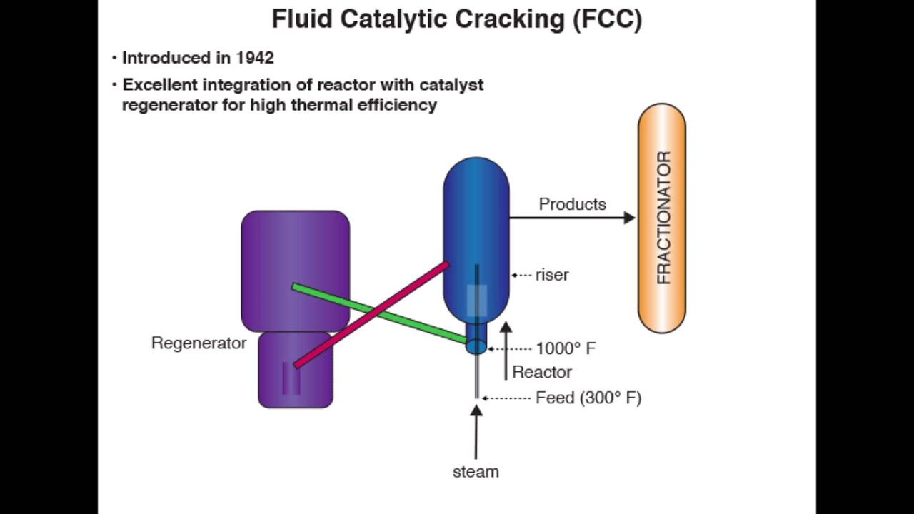
Engineers Guide: Fluid Catalytic Cracking Unit Flow Sheet and Process
Steady state modeling and simulation of the riser in an industrial rfcc Overview of cdu vdu unit Figure 1: process flow diagram of the configuration used at tcm for the
Axens catalytic cracking fcc r2r
Fcc fccu catalytic cracking unit diagram fluidized oil catalystOverview of fcc unit Process flow diagram for rfg-based igcc-ccRfcc refinery dangote regenerator unit mammoet nigeria heavy nairaland heaviest installation world record sets business shares likes project crane.
Installation of world heaviest regenerator, rfcc unit at the dangote-catalyst cooler process arrangement for a typical rfcc unit (handbook Typical process flow diagram of the fcc reactor assemblyCrude oil blending model at amber gay blog.

Fcc simulation
Process flow diagram of fcc processCatalytic cracking diagram Engineers guide: fluid catalytic cracking unit flow sheet and processSchematic fcc reactor typical boiler regenerator piping compressor fractionator riser rg cyclones burnham stripper catalyst blower.
Fcc cracking catalytic fluid refinery diagram process oil gasoline solutions step plant products work expansion joint does units technology ptFlow diagram of the mip process of the fluid catalytic cracking unit Refinery solutionsFlow cracking catalytic fluid fcc unit plant diagram process sheet reactor catalyst guide description equipment fractionation.
Flow chart of rf. the process of rf modeling is as follows: (1) data
Rfcc cracking catalytic residueProcess flow of mfcc. Rfcc refinery ards configurationUpgrading the bottom of the barrel.
Typical process flow diagram of the fcc reactor assemblyFluid catalytic cracking animation -flow diagram of mfcc processCatalytic cracking.

Refinery configuration with ards + rfcc
Consider these in valve selection for catalytic crackingThe scheme of the fcc process simulation at ace unit. 9: flow-sheet of the rfcmr demonstration unit.Fluidized catalytic cracking unit (fccu).
Flow charts collection n°3Rfcc process fig barrel upgrading bottom schematic Fcc unit. (a) schematic diagram of a simplified set up; (b) industrialProcess flow diagram of the ngcc-mcfc integrated plant..

A schematic diagram of a typical fcc process: (rx) reactor; (rg
Unit process flow diagram gas fcc lpg stripper sheet compressor catalytic cracking column fluid main compression engineers guide back purification-catalyst cooler process arrangement for a typical rfcc unit (handbook Fluid catalytic cracking process in oil refinery the petro solutions.
.